English
 中文简体
中文简体 русский
 Español
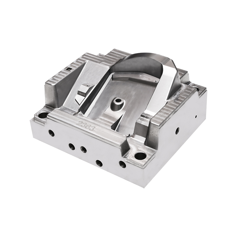
A BMC mold is a compression or injection tool used to shape bulk molding compound — a thermoset composite made from chopped glass fibers, resin, fillers, and various additives — into finished parts. The compound flows under heat and pressure, fills the cavity, cures in place, and ejects as a rigid, dimensionally stable component. That description makes it sound almost mechanical, but the engineering involved in getting it right is anything but simple.
The starting point is always the part geometry. BMC flows differently from thermoplastics. It's thicker, it carries fiber reinforcement that can orient under flow, and it doesn't tolerate sharp corners or abrupt wall thickness changes the way some other materials do. A BMC mold cavity needs to be designed with these characteristics in mind from the beginning — not adapted to them after the sampling run. Draft angles need to be generous enough to allow clean ejection without surface tearing. Wall thickness should stay as uniform as possible to prevent differential cure rates that to warpage or internal stress concentrations.
Surface finish inside the BMC mold cavity affects more than appearance. A highly polished surface reduces sticking and allows cleaner release, which matters when parts have complex geometry or thin walls that could tear during ejection. Texture, on the other hand, is sometimes applied deliberately — to mask minor surface variations in the molded part, or to meet specific aesthetic requirements for consumer-facing components.
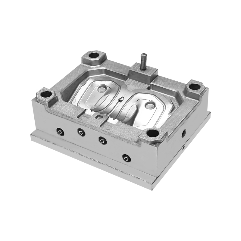
Gate location and venting are two details that get underestimated in early design reviews. Where the material enters the cavity determines how it flows, where the fiber reinforcement orients, and where weld lines form if multiple flow fronts meet. In structural parts, weld lines are weak points — they need to be placed where stress concentrations are low, which sometimes conflicts with the gate position that would be easiest to machine or trim. Venting, meanwhile, needs to allow displaced air and volatiles to escape during the cure cycle without leaving burn marks or short shots. A BMC mold with inadequate venting produces scrap at a rate that climbs steadily and is frustrating to diagnose because the symptoms can look like a material or process problem rather than a tooling one.
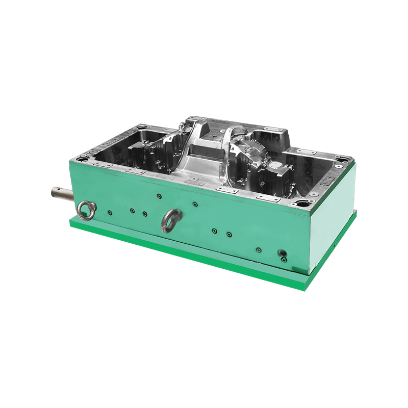
Ejector pin placement follows a similar logic. The pins need to be positioned where they can push the part free without leaving visible witness marks on show surfaces, and where the local geometry can handle the ejection force without cracking or deforming. For parts with deep ribs or bosses, sleeve ejectors or blade ejectors sometimes work better than round pins — but they add complexity to the mold base and require more careful alignment. These are exactly the kinds of tradeoffs that experienced mold designers work through early, because retrofitting ejection systems after a tool is built is expensive and often imprecise.
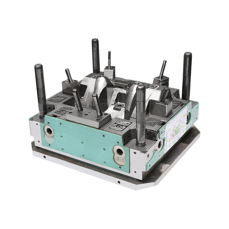
What makes BMC mold engineering genuinely interesting — and genuinely demanding — is that none of these variables operate independently. A change to gate location affects flow and fiber orientation. A change in wall thickness shifts cure time and ejection force requirements. Steel hardness influences polish quality, which affects release behavior. Getting a BMC tool right the time requires holding all of these relationships in mind simultaneously, which is why experienced toolmakers in this space are worth finding before the design is finalized rather than after the set of samples comes back wrong.