English
 中文简体
中文简体 русский
 Español
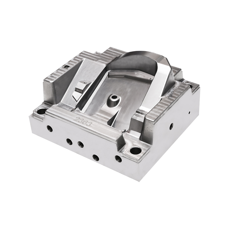
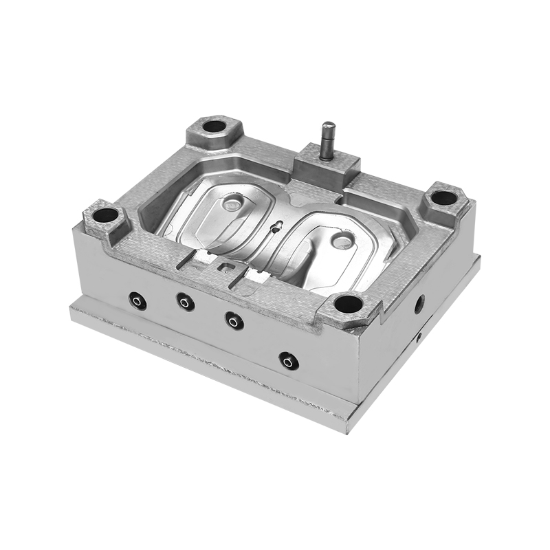
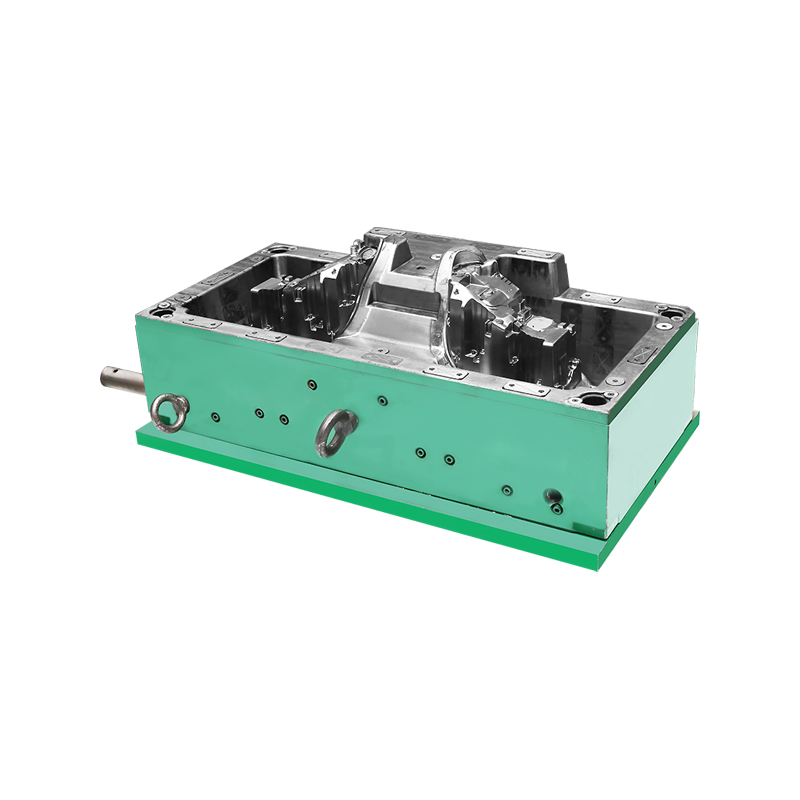
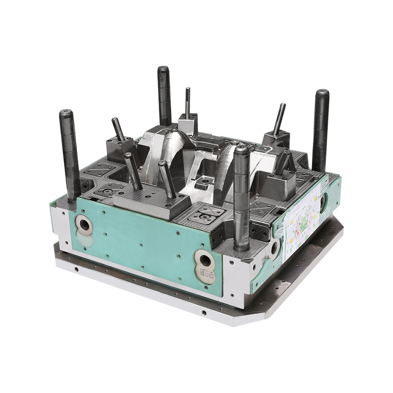
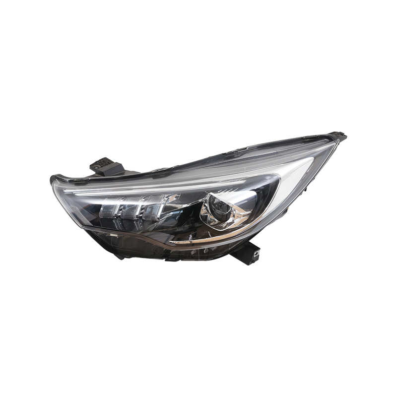
Auto Lamp Mould tools form the plastic housings and lenses used in vehicle lighting systems. Factories machine these precision moulds from hardened steel so they can withstand repeated injection cycles of polycarbonate or acrylic resins. Production centers on cavity accuracy, cooling efficiency, and surface finish that deliver consistent optical parts for automotive assembly lines. Teams focus on dimensional control and material flow that keep output aligned with supplier schedules.
Materials Selected for Auto Lamp Mould
Tool steel grades form the main body of an Auto Lamp Mould because they resist wear under high injection pressures and temperatures. Blocks receive heat treatment to reach the hardness required for long production runs. Surface coatings or polishing improve release properties and reduce friction when plastic parts eject from the cavities. Cooling channels drilled into the steel circulate water or oil to manage heat during each cycle.
Inserts made from the same steel family handle complex lens textures or mounting features. These inserts allow changes to specific areas without replacing the entire mould base. Suppliers deliver steel with certified hardness and uniformity so machining centers can maintain tight tolerances across the cavity surfaces. The combination of base steel and inserts supports stable performance across different lamp designs.
Design Elements in Auto Lamp Mould
Cavity layout determines how many lamp housings or lenses form in a single shot. Multi-cavity configurations raise output while keeping part geometry identical. Core and cavity surfaces include optical textures that create the required light diffusion or reflection patterns. Hot runner systems deliver molten resin evenly to each cavity, limiting material waste and improving fill balance.
Ejection systems use pins or plates positioned to release parts without marking critical optical surfaces. Alignment features keep the two mould halves matched so wall thickness stays uniform. Design teams adjust these elements according to the specific lamp shape and resin grade, ensuring the Auto Lamp Mould matches downstream assembly requirements.
Machining and Assembly of Auto Lamp Mould
CNC machining centers cut the steel blocks according to detailed cavity drawings. Electrodes for electrical discharge machining shape fine details that cutting tools cannot reach. After rough machining, surfaces undergo polishing to achieve the clarity needed for transparent lenses. Cooling circuits receive final drilling and pressure testing before the mould halves assemble.
Assembly stations mount hot runner manifolds, temperature sensors, and ejection components. Workers verify alignment and clamp force so the mould operates smoothly on injection machines. Trial runs confirm that resin fills the cavities completely and that parts release cleanly. These steps prepare the Auto Lamp Mould for continuous use in automotive parts production.
Practical Adjustments During Production Runs
Operators adjust injection speed, pressure, and cooling time based on resin batch characteristics. Changing insert sets allows the same mould base to produce different lens patterns or housing variants. Temperature control on the hot runner keeps material flow consistent from the shot to the last. These adjustments stay within established process windows so cycle times remain predictable.
Inspection stations check part weight, optical clarity, and critical dimensions after each shift. Feedback from these checks guides minor refinements to packing pressure or cooling flow. Documentation of each adjustment supports traceability for automotive customers who require detailed process records. This structured approach keeps Auto Lamp Mould output aligned with the volume and quality expected by vehicle component partners.